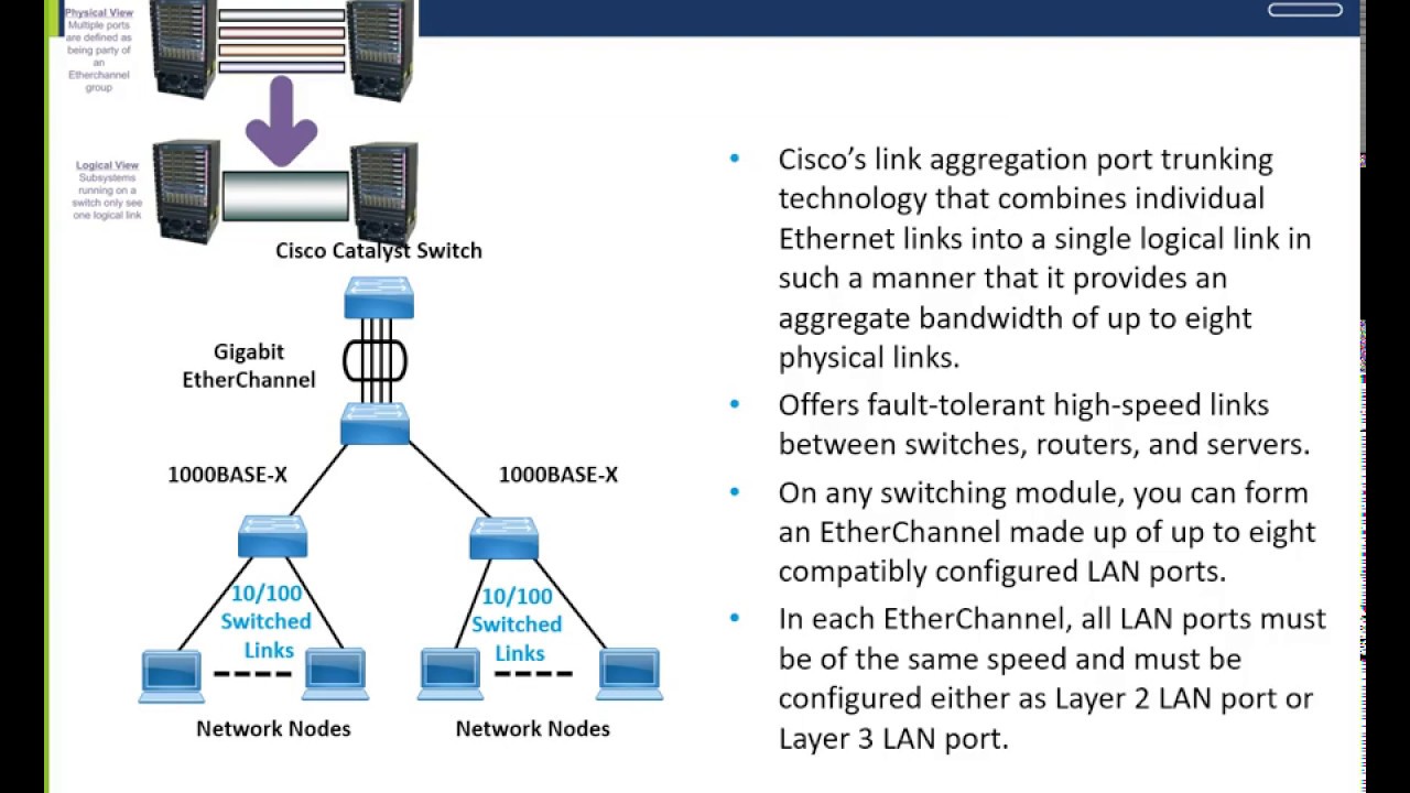
What is the Ether channel
As we have seen in this chapter, STP works by blocking links that are not necessary in order to avoid layer 2 loops, but picture the scenario shown below.
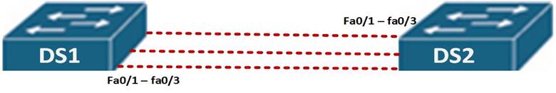
In this scenario, the two switches; DS1 and DS2 are interconnected by three fast Ethernet links for redundancy, this can be a major loop issue and as such, when STP is active on the switches, 2 of the links will be blocked and only one link will be in use.
This means that only 100Mbit will be in use whilst if all links were active, we would have 300Mbits in use which would be more effective use of the bandwidth between the switches.
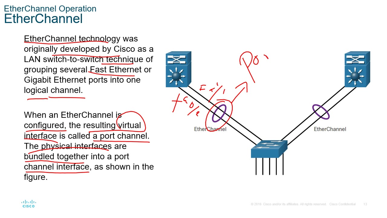
Ether channel, is a way to use bandwidth on redundant links more effectively, by aggregating links and making them into a single logical connection as depicted below.

As you can see from our modified topology, the three fastEthernet Links have been bundled up into a single logical connection which is port-channel 1.
Verifying EtherChannel
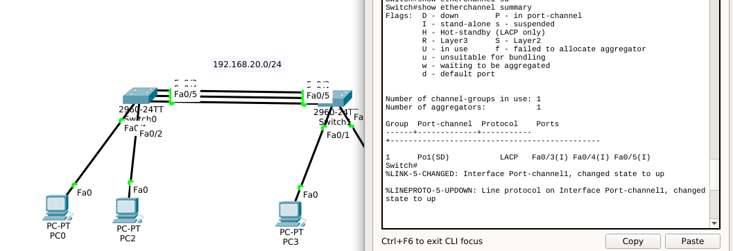
One place to go to verify your EtherChannel bundle is on the switch. We’re creating a logical interface out of thin air, and so we can’t see it as a regular interface. This looks like a physical interface, it’s not. But we can see that it is up-up.
I’ll be honest though. We don’t usually look at it and troubleshoot it with this command. When we’re verifying EtherChannel, we need to dig deeper and we need to use commands that are specific and can get the magnifying glass to look at things like the member ports.
I said that there were two things that you really want to have mastered for this discussion. This for me is the second. The first was knowing your protocols and the parameters that set which protocol. The next is this output and I would want you to know the flags, the key words that we see here. So this is a great command: show etherchannel summary and look at all those flags up top. That’s a lot and we should know how to use those flags. Down below it says, the number of channel groups, one. Great. That’s what we had configured before but let’s go from left to right. Group, well that’s just the group number.
Then we see the logical name and this is where we need to be very careful about reading. It says, Po1 for port-channel 1, SU. In the real world I would like to see SU or RU. So what’s the upper case S here? Well I want you to find it in the flags. S says layer two, which means this is not a router port. I had said that you can use this on layer three EtherChannel bundles and a layer three EtherChannel bundle would have an R. So for me the only things that I want to see here are S or R, and we have to be mindful of the capitalization, by the way, because a lower case s can come up elsewhere. OK. So that’s the S, for Switched essentially. Is it Switched or Routed? The next one is, U. This is a big deal. U says, in use. So you don’t want to see anything other than a U here, like a D. It’s a very possible value you could see, a D. U says Up. It says, in Use but I think of it as Up. OK. Then protocol LACP Active and Passive, settings.
Then we have our ports. So here, we would list the two to however many ports we have in EtherChannel bundle. And then there is a P here and that P says we’re participating in the port channel. It’s possible to see things like suspended here, OK? You don’t want to see that. So knowing that decode for me is the second big takeaway from this chapter. You should know how to read the output and obtain the output. So show etherchannel summary, pretty important command.
By far, the last show command is the most important show command. You want to be able to read through that output inside and out, up and down, side to side without a problem. The show etherchannel Port-channel command allows us to dive into the specifics about our port-channel.
We can see the number of groups we have configured, in this example, one. And the first port-channel we’re looking at is port-channel one. We can see aging, timers, how long it has been available for, the protocol, LACP, and the ports in the port-channel. Similar information that we just saw in the show etherchannel summary command, but here we can see the load as well. How much load on an average is each link utilizing. The ports 0/0, 0/1 and then our state, the EC state – Active, Active. Where have I heard that word before? It’s one of the modes. It’s one of the modes directly related to LACP.
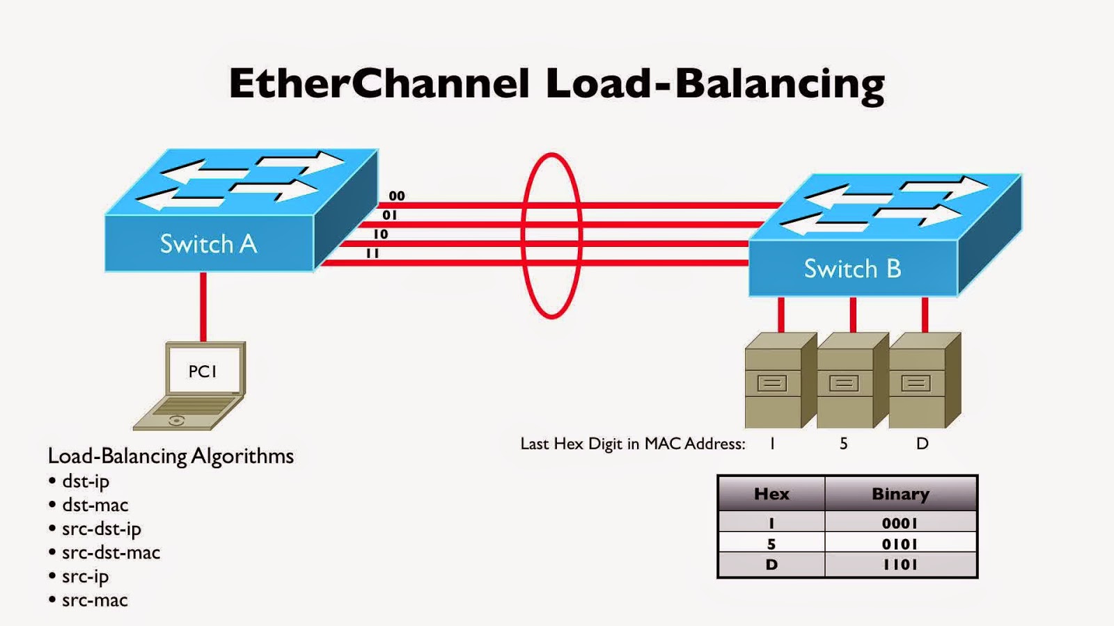
In most of the cases the load isn’t 50-50 and this is because of the underlying frame forwarding that happens. It’s not a round-robin fashion. It doesn’t say, frame one goes here, frame one goes the other one. No. Instead, it’s based on the number of bits that you see there. Number of bits says, here is our hashing algorithm, which takes fields in the headers of the frames and based on the output of those, chooses which port it goes down. So in a more advanced class, we might teach you about altering where those bits are pulled from. Do we pull it from the layer two header with MAC, short for Media Access Control addresses? Do we look at IP addresses, source, and destination? And it is very chassis dependent, as well. Some chassis give you fewer options. So this is kind of a nice to see output. And if things were wildly misbehaving as in, you’re expecting double the throughput but then you came here and you saw a load of 95 and 5. Well then, you might have to figure out, how do I change my load balancing strategy to get a better distribution of traffic?
Блог о модемах, роутерах и gpon ont терминалах.
В рамках сегодняшней статьи я расскажу как настроить физический порт на коммутаторах Cisco в режиме Access и Trunk, а так же каким образом заставить его работать в так называемом гибридном режиме. Давайте подробнее разберемся что из себя представляет каждый из этих типов и каким образом он конфигурируется. Для примера рассмотрим Cisco Catalyst 2950. Для 2960, 2970, 3550, 3560 и ME3400 — все действия те же самые. Первым делом, надо зайти в режим глобальной конфигурации устройства и войти в параметры нужного порта:
1. Access Port. Это оконечный порт коммутатора, который смотрит в сторону оконечного клиентского устройства доступа — модема, WiFi-роутера или просто компьютера, к которому трафик идет уже в нетегированном виде. Конфиг выглядит вот так:
С помощью команды switchport mode access мы переводим порт в режим аксесс. При этом в сторону этого порта будет идти трафик по так называемой native vlan, которой как правило выступает vlan 1.
Если же мы наберем команду:
В этом случае пойдет трафик, принадлежащий vlan 310.
2. Trunk port. Такой вариант используется в том случае, когда организуется канал между двумя сетевыми устройствами — то есть с другой стороны стоит коммутатор или маршрутизатор. Поэтому транковый порт в некоторых случаях называют магистральным. Через него передается трафик по нескольким vlan. Конфиг на 2950 выглядит так:
То есть, для catalyst 2950 достаточно в параметрах порта прописать строку:
Если у Вас коммутатор 2960 и выше, то необходимо ещё ввести команду:
Всё дело в том, что 2950 умеют работать только с 802.1q, в то время, как более новые устройства поддерживают инкапсуляцию ISL, поэтому тип инкапсуляции на порту надо указывать явно.
Если надо разрешить проходить через транковый порт только определенным vlan’ам — указываем их с помощью команды switchport trunk alloved vlan и указываем через запятую идентификаторы. В моем случае для vlan 310 и 555 команда будет выглядеть так:
3. Hybrid port. Коммутаторы Cisco не позволяют явно прописать на порту type Hybrid, но сделать порт гибридным можно указав для транкового порта свой nativ vlan. Для примера, я сделаю trunk-порт, на котором в транке будет vlan 555, а в то же время, весь нетегированный трафик на порту будет заворачиваться во vlan 310:
Cоздание vlan
Переходим от слов к делу и делаем vlan на cisco,
sh vlan
Видим что есть vlan 1 и все порты по умолчанию в нем.
Как создать и настроить vlan в Cisco на примере Cisco 2960+48TC-S-01
Создадим vlan 2 для отдела бухгалтерии. Заходим в режим конфигурирования.
vlan 2
name buh
exit
Как создать и настроить vlan в Cisco на примере Cisco 2960+48TC-S-02
Общая схема такая
Как создать и настроить vlan в Cisco на примере Cisco 2960+48TC-S-03
Теперь подключим интерфейсы Fa0/1 и Fa0/2 к которым подключены компьютеры бухгалтерии к vlan2
interface fastEthernet 0/1
Как создать и настроить vlan в Cisco на примере Cisco 2960+48TC-S-04
Теперь переключим vlan для данного интерфейса.
switchport access vlan 2
end
wr
Как создать и настроить vlan в Cisco на примере Cisco 2960+48TC-S-05
Вводим sh vlan и видим появился vlan 2 и в нем нужный интерфейс.
Как создать и настроить vlan в Cisco на примере Cisco 2960+48TC-S-06
Сделаем тоже самое для Fa0/2
interface fastEthernet 0/2
switchport access vlan 2 end
wr
Как создать и настроить vlan в Cisco на примере Cisco 2960+48TC-S-07
Как создать и настроить vlan в Cisco на примере Cisco 2960+48TC-S-08
Создадим vlan 3 для user
name user
exit
Как создать и настроить vlan в Cisco на примере Cisco 2960+48TC-S-09
Добавим vlan 3 ip адрес 192.168.3.254


interface vlan 3
ip address 192.168.3.254 255.255.255.0
end
Как создать и настроить vlan в Cisco на примере Cisco 2960+48TC-S10
Теперь проверим наш ip на vlan3 на vlan 2 я настраивал аналогично
Как создать и настроить vlan в Cisco на примере Cisco 2960+48TC-S11
Теперь подключим интерфейсы Fa0/3 и Fa0/4 к которым подключены компьютеры пользователей к vlan3
interface fastEthernet 0/3
switchport access vlan 3 exit
interface fastEthernet 0/4
switchport mode access
switchport access vlan 3 wr
Как создать и настроить vlan в Cisco на примере Cisco 2960+48TC-S12
Как создать и настроить vlan в Cisco на примере Cisco 2960+48TC-S13
Как создать и настроить vlan в Cisco на примере Cisco 2960+48TC-S14
do sh run
Как создать и настроить vlan в Cisco на примере Cisco 2960+48TC-S15
На этом все vlan настроены в следующей части мы поговорим про trunk порты которые позволяют настроить коммутатор в коммутатор
Подключение и настройка Cisco Catalyst 2960 имеет свои нюансы и несколько отличается от подключения оборудования других производителей. Первоначальная настройка потребует наличие фирменного плоского кабеля RJ-45–RS-232 (в голубой оплетке, поставляется с оборудованием) и присутствие на материнской плате компьютера COM-порта, через который будут выполняться процедуры настройки.
На материнских платах современных компьютеров COM-порт отсутствует, поэтому чтобы провести настройку потребуется специальный переходник. Компания Cisco в своем оборудовании для консоли использует разъемы Mini–USB. Чтобы провести настройку через порт Mini–USB следует скачать программу cisco usb console driver.
Нестандартизованные технологии [ править | править код ]
Большинство решений для агрегирования гигабитных каналов основывается на стандарте IEEE 802.3ad. Однако нестандартизованные протоколы других фирм существовали ещё до принятия этого стандарта, некоторые из них используются до сих пор. Эти протоколы в большинстве своём работают исключительно с продукцией одной компании или продукцией одной линии. Некоторые из них имеют определённые преимущества перед стандартом, например EtherChannel, используемый Cisco, поддерживает разные режимы посылки пакетов, тогда как 802.3ad поддерживает только стандартный режим. Среди других нестандартных протоколов агрегации — Duralink Trunking (Adaptec), MLT (multi link trunking, Nortel).
К середине 2000-х годов большинство производителей перешли на выпуск сетевых устройств с поддержкой стандарта IEEE 802.3ad, что в принципе должно обеспечивать возможность совместной работы устройств различных марок. Однако на практике некоторые сочетания могут оказаться неработоспособными, поэтому в спецификациях зачастую специально уточняется возможность совместной работы тех или иных устройств.
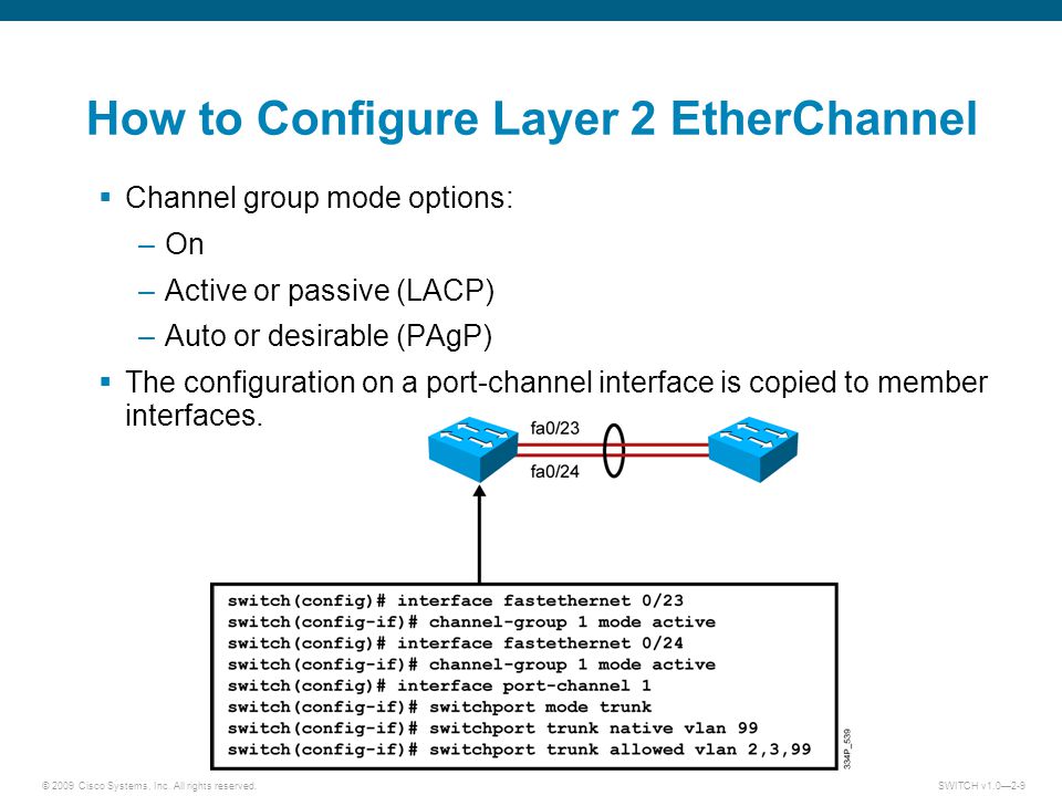
Configuration Guidelines
There are some important guidelines and restrictions for configuring the port channel:-
- EtherChannel support : All the ethernet interfaces must support port channel as there should not be any problem in the physical layer of the interface.
- Speed and duplex : Configure all interfaces in an EtherChannel to operate at the same speed and in the same duplex mode.
- VLAN match : All interfaces in the EtherChannel must be in the same VLAN or should be act as trunking.
- Range of VLANs : An EtherChannel supports the same allowed range of VLANs on all the interfaces in a trunking EtherChannel. If the allowed range of VLANs is not the same, the interfaces do not form an EtherChannel, even when they are set to auto or desirable mode.
Configuration
The configuration shown here is relevant to a Cisco IOS switch. Similar config is used on a router or Nexus switch. This may be quite different to other vendors.
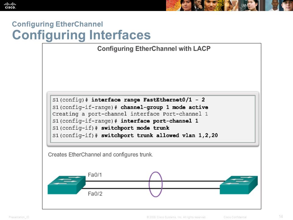
Interface Configuration
Each interface is configured by adding it to a particular channel-group, and chosing the mode.
The mode can be:
| Mode | Technology | Usage |
|---|---|---|
| On | Static | Turns the channel on unconditionally |
| Active | LACP | Actively attempts to form a channel |
| Passive | LACP | Will only form a channel if the other end is in active mode |
| Desirable | PAgP | Actively attempts to form a channel |
| Auto | PAgP | Will only form a channel if the other end is in desirable mode |
An example of this configuration is:
interface range GigabitEthernet0/1-4
  description Member Port
  channel-group 1 mode active
  no shutdown
The configuration above uses the range option to configure multiple interfaces at once. This is optional, individual interfaces can be configured one at a time, as long as they’re in the same group.
The channel-group number corresponds to the Administrative Key when LACP is used.
Port-Channel Configuration
After one or more interfaces have been added to a channel-group, a virtual interface called a port-channel is created:
show running-config interface port-channel 1
Building configuration...

Current configuration : 122 bytes
!
interface Port-channel1
end
This can be configured just like a normal interface. Much of the configuration on the port-channel will be applied directly to the member interfaces. One exception to this is the description, which can be different on each physical interface and the port-channel.
interface port-channel 1
  description EtherChannel
  switchport trunk encapsulation dot1q
  switchport mode trunk


show running-config interface gigabit 0/1
Building configuration...

Current configuration : 122 bytes
!
interface gigabit 0/1
  description MemberPort
  switchport trunk encapsulation dot1q
  switchport mode trunk
end
Настройка EtherChannel на Cisco
4 минуты чтения
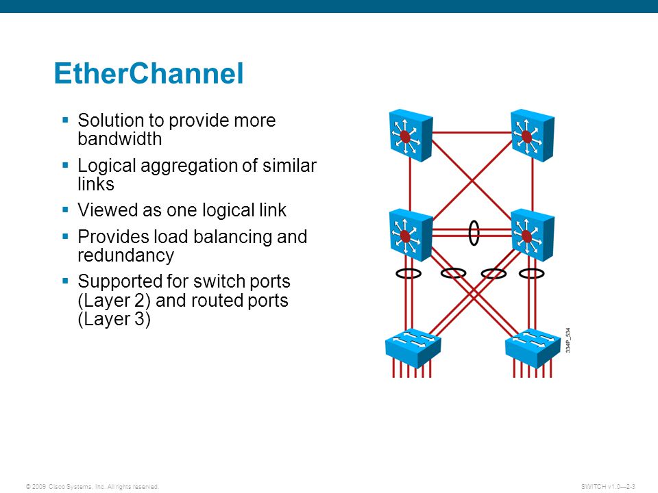
В этой статье мы расскажем как настроить LACP (Link Aggregation Control Protocol) И PAgP (Port Aggregation Protocol), которые носят гордое название EtherChannels — агрегирование каналов.
На самом деле EtherChannel это технология агрегации (объединения) каналов. Это означает, что мы можем объединить несколько линков в один логический, что позволит увеличить пропускную способность между коммутаторами.
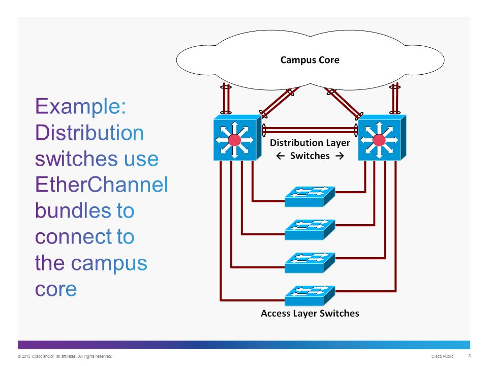
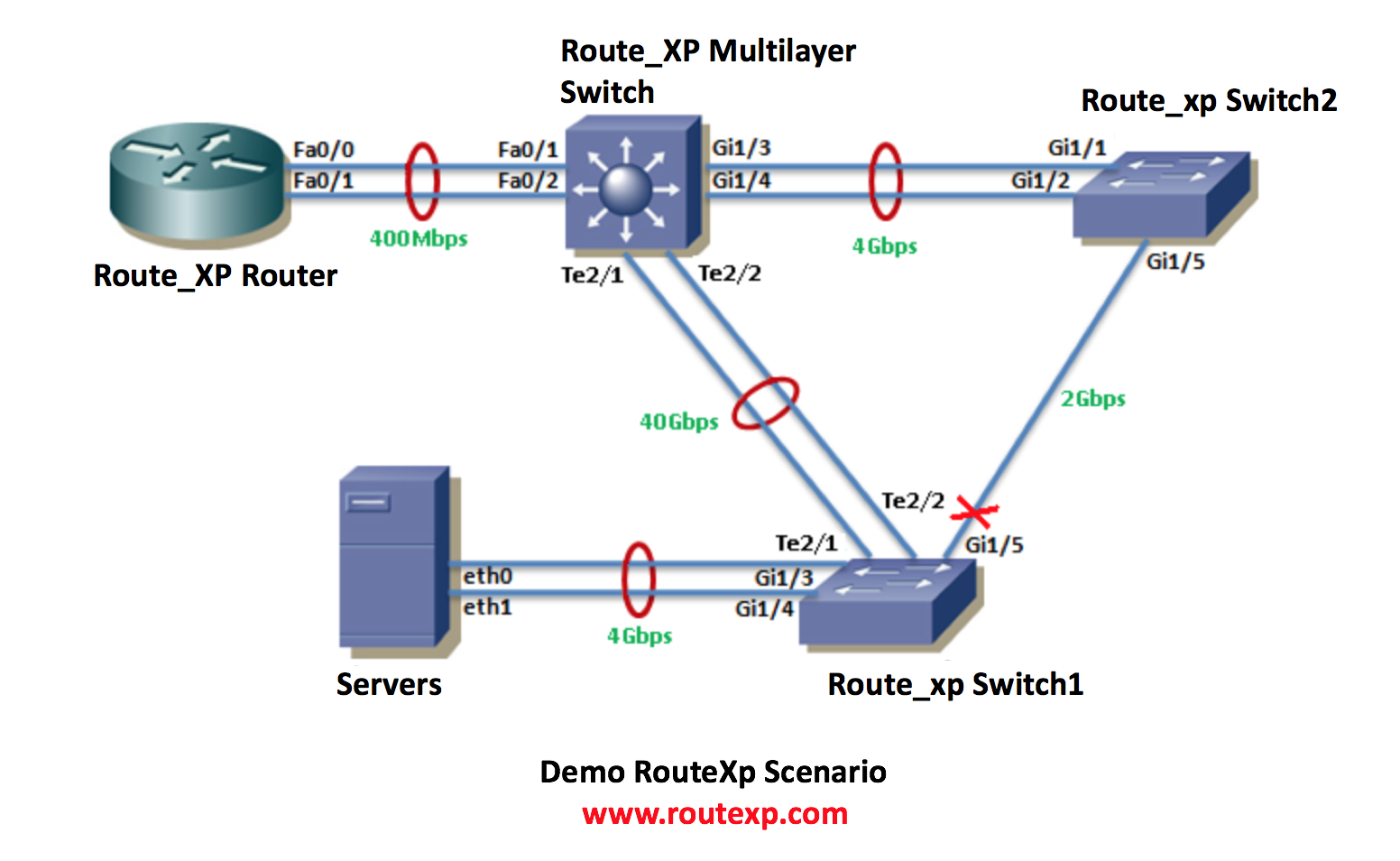
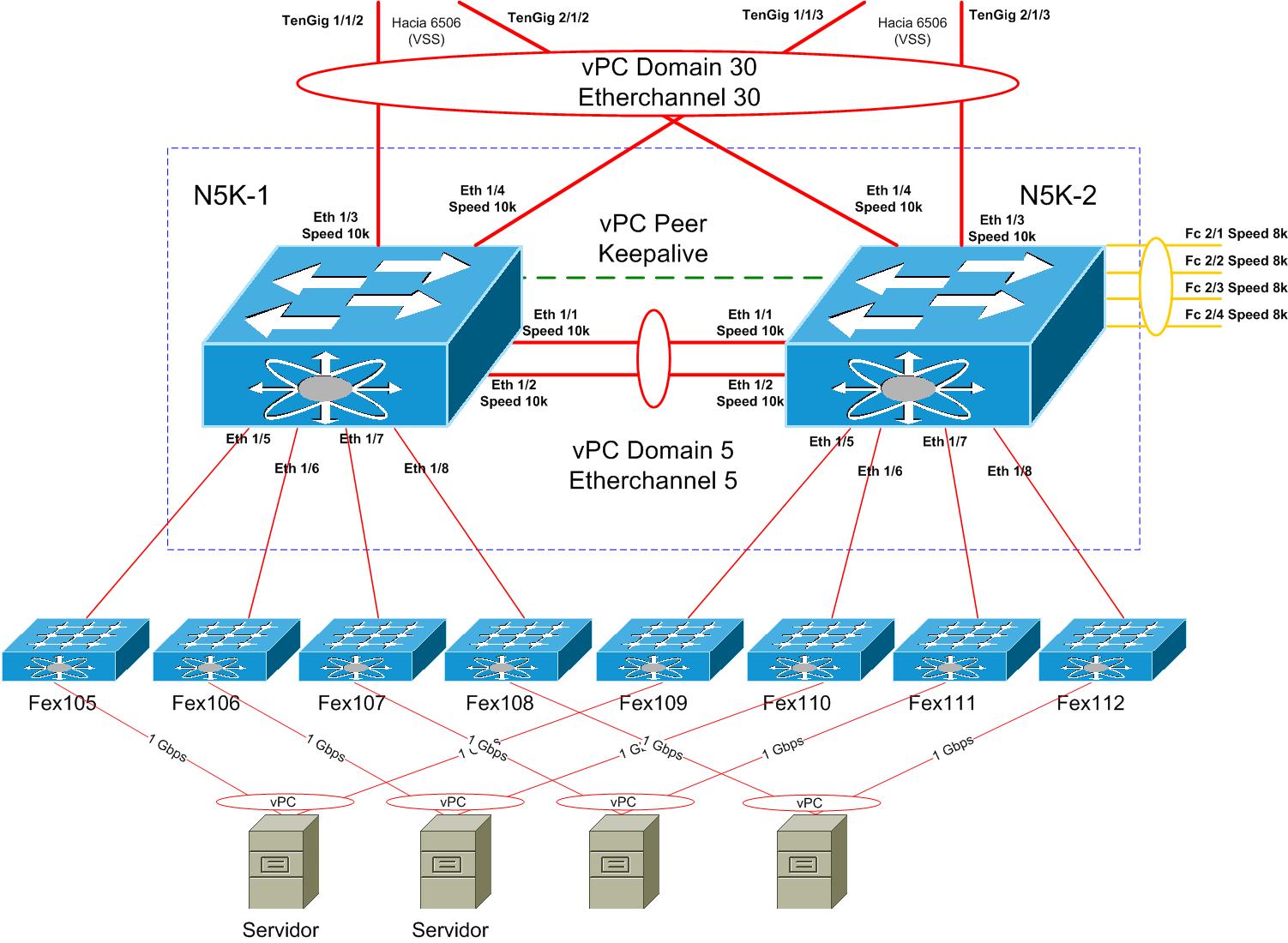
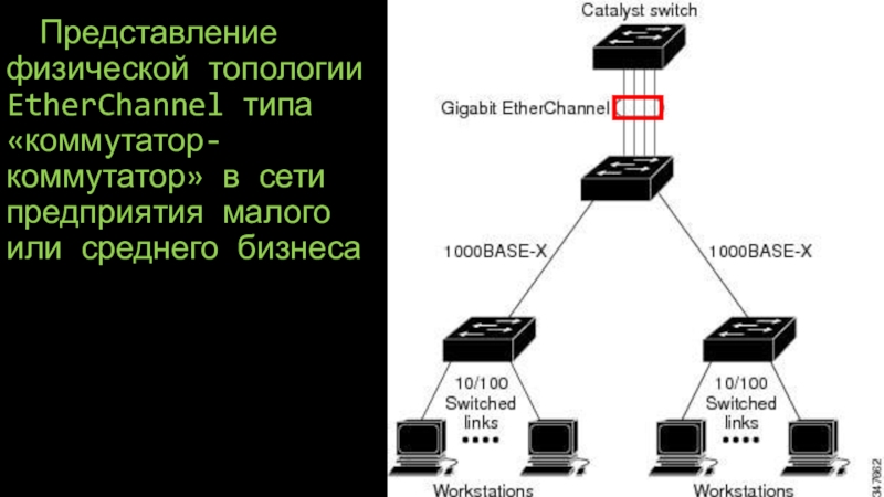
Пример использования
Взглянем на схему ниже:
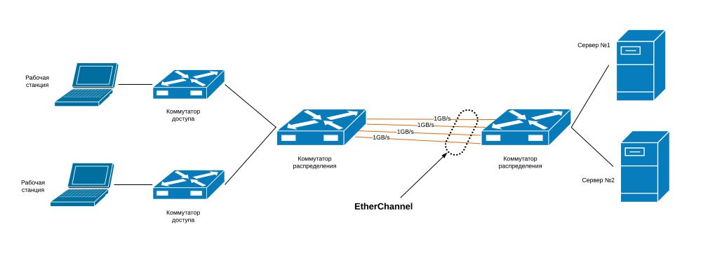
В рамках данной схемы мы имеем серверную инфраструктуру, которая подключена в коммутатору распределения (distribution switch) через свой коммутатор. За коммутатором распределения сидят коммутаторы доступы, за которым расположились пользовательские рабочие станции:
Если мы подключим два коммутатор линком в 1ГБ/сек, то потенциально, мы можем столкнуться с проблемой «бутылочного горлышка», то есть узкого места. Тогда пользователи испытают проблемы с доступом к серверной ферме.
Используя технологию EtherChannel, мы можем объединить до 8 интерфейсов (физических) в один логический линк (агрегация портов, Port-Channel) и трафик будет распределяться между физическими портами равномерно (балансируя нагрузку).
В нашем примере мы объединили 4 (четыре) гигабитных линка между рабочими станциями и серверами в один, с пропускной способностью 4ГБ/сек. Это увеличило общую пропускную способность и добавило отказоустойчивость линков!
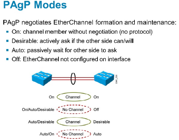
Режимы EtherChannel
Каждый из протоколов LACP или PAgP имеет по 3 режима работы, которые определяют режим его активности (инициализировать ли построение агрегации со своей стороны, или ждать сигнал с удаленной стороны):
- LACP Modes: ON, ACTIVE, PASSIVE;
- PAgP Modes: ON, DESIRABLE, AUTO;
Давайте посмотрим, в каком из случае будет установлено соединение EtherChannel при различных режимах настройки. Для LACP:
| Коммутатор №1 | Коммутатор №2 | Установится ли EtherChannel? |
|---|---|---|
| ON | ON | Да |
| ACTIVE | ACTIVE/PASSIVE | Да |
| ON/ACTIVE/PASSIVE | Not configured (off) | Нет |
| ON | ACTIVE | Нет |
| PASSIVE/ON | PASSIVE | Нет |
Теперь разберемся с PAgP:
| Коммутатор №1 | Коммутатор №2 | Установится ли EtherChannel? |
|---|---|---|
| ON | ON | Да |
| DESIRABLE | DESIRABLE/AUTO | Да |
| ON/DESIRABLE/AUTO | Not configured (off) | Нет |
| ON | DESIRABLE | Нет |
| AUTO / ON | AUTO | Нет |
Настройка
Ок, предположим, что порты с Gi0/0 по Gi0/3 буду использованы для агрегации EtherChannel. Лучше всего настроить логический интерфейс (агрегированный) в качестве транка, чтобы пропускать VLAN между коммутаторами.


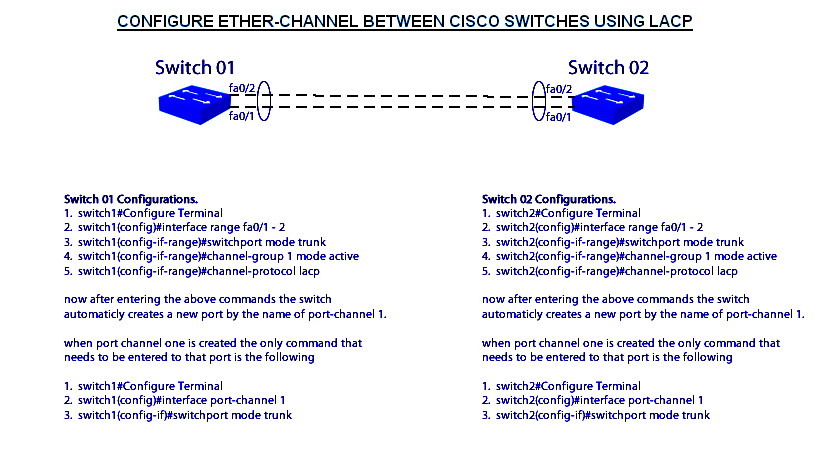
Поднимаем LACP
В нашем случае switch1 будет активном (Active) режиме, а switch2 будет в пассивном (Passive) режиме.
Поднимаем PAgP
В этом случае switch1 будет Desirable — режиме, а switch2 будет в автоматическом (Auto) режиме.
Полезные команды
Вот некоторые команды, которые могут понадобиться вам в работе с EtherChannel:
Пожалуйста, расскажите почему?
Агрегирование каналов (англ. link aggregation ) — технологии объединения нескольких параллельных каналов передачи данных в сетях Ethernet в один логический, позволяющие увеличить пропускную способность и повысить надёжность. В различных конкретных реализациях агрегирования используются альтернативные наименования: транкинг портов (англ. port trunking ), связывание каналов ( link bundling ), склейка адаптеров ( NIC bonding ), сопряжение адаптеров ( NIC teaming ).
LACP (англ. link aggregation control protocol ) — открытый стандартный протокол агрегирования каналов, описанный в документах IEEE 802.3ad и IEEE 802.1aq. Многие производители для своих продуктов используют не стандарт, а патентованные или закрытые технологии, например, Cisco применяет технологию EtherChannel (разработанную в начале 1990-х годов компанией Kalpana ), а также нестандартный протокол PAgP.
Главное преимущество агрегирования каналов в том, что потенциально повышается полоса пропускания: в идеальных условиях полоса может достичь суммы полос пропускания объединённых каналов. Другое преимущество — «горячее» резервирование линий связи: в случае отказа одного из агрегируемых каналов трафик без прерывания сервиса посылается через оставшиеся, а после восстановления отказавшего канала он автоматически включается в работу .
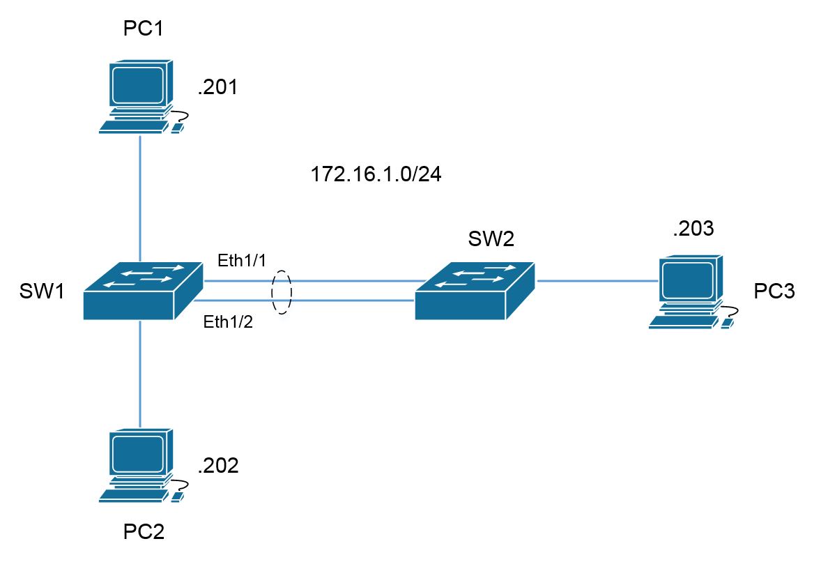
Делаем port-channel
Время идёт — компании растут, осваивают новые рынки и охватывают новые зоны. Соответственно разрастается и их инфраструктура. Рано или поздно, каждый администратор сталкивается с необходимостью расширения пропускной способности канала до определённой точки или организации резервного канала
Порой возможности качественно (например заменой медного канала на оптический) нет возможности — материальной или иной — не важно. В этом случае на помощь придёт очень удобная функция организации Port-channel
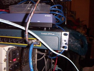
Рассмотрим настройку Port-channel на примере расширения медного 100-мегабитного канала между двумя коммутаторами Cisco Catalyst 2950 путём подключения дополнительного канала.
В моём случае необходим trunk’овый канал, поэтому указываем это при настройке интерфейса Port Channel строкой:
Теперь по очереди настраиваем оба интерфейса — в данном примере это 100-мегабитные FastEthernet-порты. Они настраиваются так же в режим trunk. Прописываем FastEthernet 1:
Теперь прописываем порт FastEthernet 2:
На принадлежность портов к интерфейсу Port-Channel 1 указывает строка:
Теперь то же самое необходимо будет прописать на втором коммутаторе с другой стороны.
Помогло? Посоветуйте друзьям!
Молодец, парень! Все доступно и понятно даже тем, кто не имел с этим дел.
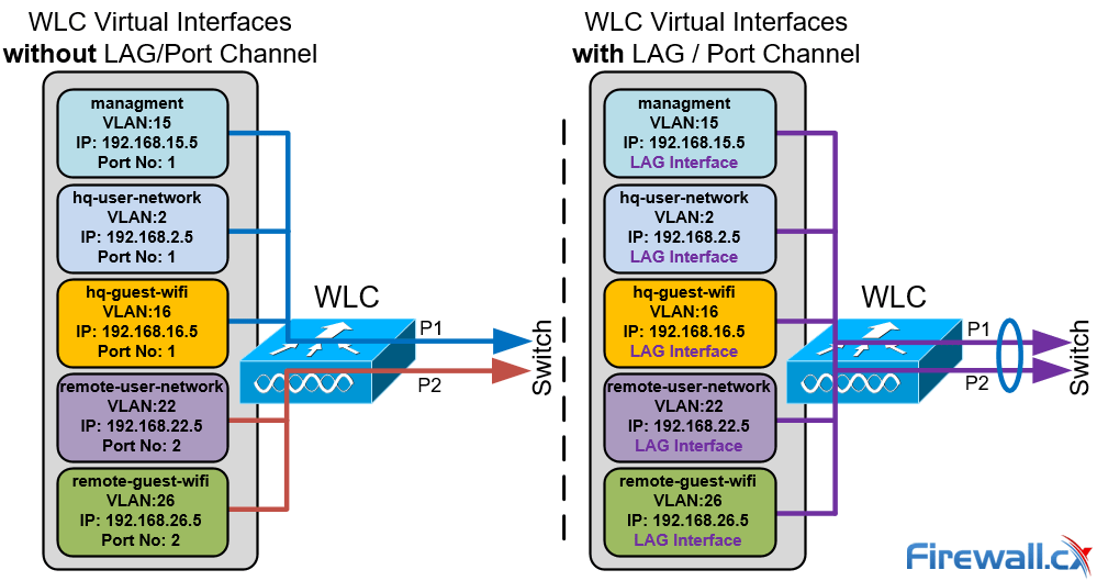
Link Aggregation Restrictions — Considerations
While LAG is the preferred method of connecting the WLC to the network there however a number of restrictions we need to be aware of to ensure we don’t stumble into any unpleasant surprises.
- On 2504 and 3504 WLCs you can bundle all 4 ports into a single link.
- On 5508 WLC you can bundle up to 8 ports into a single link.
- Link Aggregation Control Protocol (LACP) or Cisco proprietary Port Aggregation Protocol (PAgP) are not supported by the WLC. Port-Channel members must be set unconditionally to LAG (shown in the configuration below).
- Only one LAG Group is supported per WLC, you can therefore connect a WLC only to one switch unless using .
- When LAG is enabled, if a single link fails, traffic is automatically switched to the other links.
- After enabling LAG the WLC must be rebooted.
- When enabling LAG, all dynamic AP manager interfaces and untagged interfaces will be deleted. (See related article WLC Interfaces – Logical Interfaces)
- After enabling LAG, all Virtual Interfaces use the LAG interface. No backup port (under the Virtual Interface settings) is configurable:
 Click to enlarge
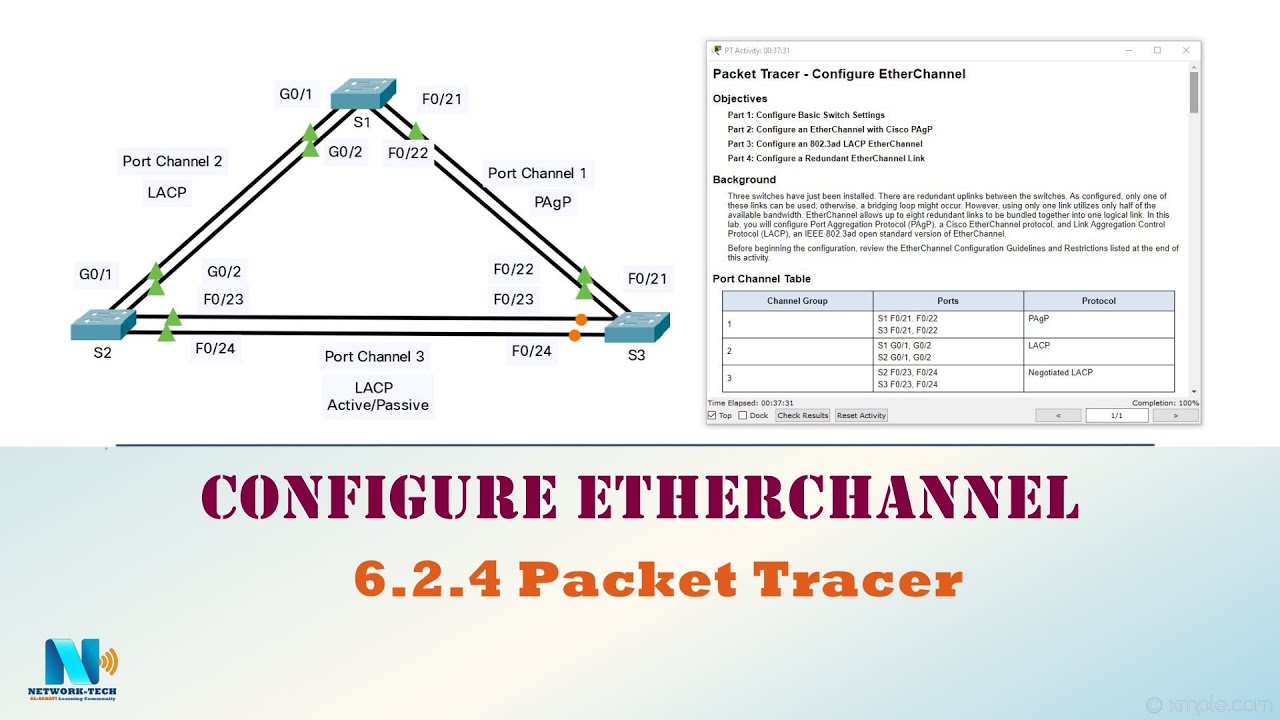
Configuring ether channel
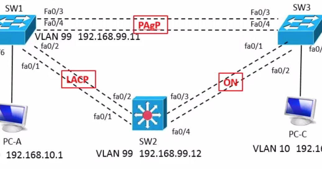
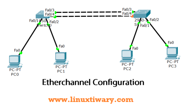
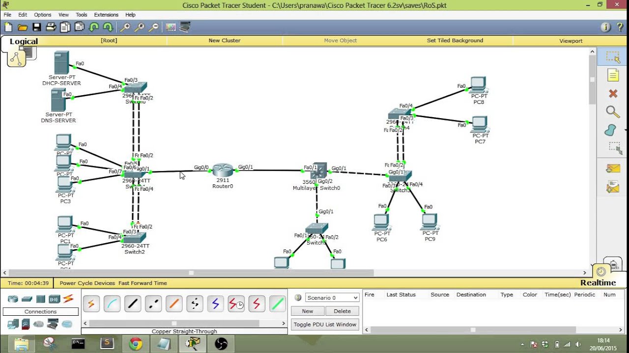
We will configure ether-channel using the scenario shown below and see how it works as well as some verification and troubleshooting commands.

In the above scenario, we are supposed to configure ether channel on the links shown. i.e. fa0/1 – fa0/3, we will use PAGP in our configuration, however, LACP configuration options are similar.
The switches are using their default configuration, and the first thing we need to verify is the number of links that are active in the topology and whether STP is blocking redundant paths.
The output of “show spanning-tree active” on both switches shows that on DS2, fa0/2 and fa0/3 are alternate ports this means that they are blocked by STP as highlighted in red. All the ports on DS1 are active since this switch was elected the root bridge.
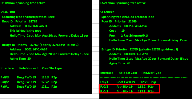
Successful configuration of the ether-channel will mean that the blocked paths will be transmitting data and will be root ports by the end of the configuration.
The first step is to enter the interface configuration mode for the three interfaces using the “interface range command” as shown below.
![]()
This will bring the interface range prompt which is denoted by “switch(config-if-range)#” as shown below.
In this mode, we can configure the ether-channel options, the two commands that we will use are:
![]()
NOTE: when the channel-protocol command is used and a negotiation protocol is enabled, the options on the channel-group command, will be limited to the options available for that protocol ONLY. I.e. if we use PAGP, the channel-group mode options we can use are “auto” and “desirable” ONLY, while for LACP, we can only use “Passive” and “active” options.
When the channel-protocol command is used, we cannot use the “ON” option in the channel-group modes.
When negotiating an aggregated link, the protocols will follow rules similar to those of negotiating trunk links as shown in the table below.
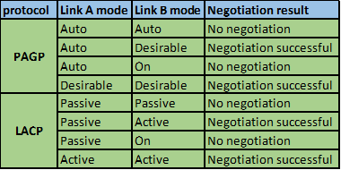
When we use the “ON” keyword on the channel-group command, we in effect activate the Ether channel exclusively, therefore if the other end of the link is in the other modes in either PAGP or LACP, the ether channel will not be active and the links will be down.
In our scenario, we will use PAGP and we will configure both sides as desirable mode.
To enable the PAGP protocol we use the “channel-protocol” command as shown below for both switches.
Next we need to configure the mode of operation as well as specify the logical port number for the ether channel. For this we use the command
![]()
In our case the logical number will be 1 and the mode will be desirable on both switches as shown below.
![]()
With this configuration, the ether channel should be up and the redundant links that were blocked by STP should now be active and we should only see the ether-channel port we have configured, and the output of the “show spanning-tree active” command on both switches should confirm this.

As you can see from the output of DS2 above, the new interface is port-channel 1, which is active and forwarding.
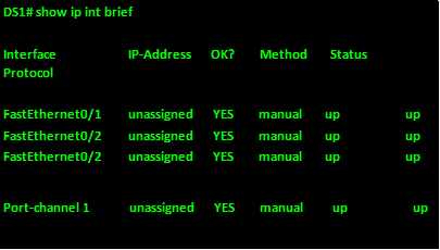
The show ip interface brief command should show us the new logical interface as well as its status as shown below.
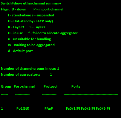
The last command that we can use to verify the status of an ether-channel, is the “show etherchannel summary” command and it will give information pertaining the configured ether-channels on the switch, the output of this command on DS2 is shown below.
With this, we come to the end of our chapter on the ETHER CHANNEL.
When using ether channels, we can effectively use the bandwidth on links that have been blocked by STP. However, take care when configuring ether channel since it may cause problems if not well implemented.
![Общие сведения о агрегирования каналов и lacp [чаво]](https://wudgleyd.ru/wp-content/uploads/1/6/a/16a477cc20a9819881149ff278383e62.png)