USING THE CONSOLE CLI
The Switch supports a console management interface that allows the user to connect to the Switch’s management agent via a serial port and a terminal or a computer running a terminal emulation program. The console can also be used over the network using the TCP/IP Telnet protocol. The console program can be used to configure the Switch to use an SNMP-based network management application over the network.
This chapter describes how to use the console interface to access the Switch, change its settings, and monitor its operation.
Note: Switch configuration settings are saved to non-volatile RAM using the save command. The current configuration will then be retained in the Switch’s NV-RAM, and reloaded when the Switch is rebooted. If the Switch is rebooted without using the save command, the last configuration saved to NV-RAM will be loaded.
Connecting to the Switch
The console interface is used by connecting the Switch to a VT100-compatible terminal or a computer running an ordinary terminal emulator program (e.g., the HyperTerminal program included with the Windows operating system) using an RS-232 DB- 9 cable or RJ45 console cable. Your terminal parameters will need to be set to:
•VT-100 compatible
•9600 baud
•8 data bits
•No parity
•One stop bit
•No flow control
Users can also access the same functions over a Telnet interface. Once users have set an IP address for your Switch, users can use a Telnet program (in VT-100 compatible terminal mode) to access and control the Switch. All of the screens are identical, whether accessed from the console port or from a Telnet interface.
After the Switch reboots and users have logged in, the console looks like this:
DES-3200-28 Fast Ethernet Switch
Command Line Interface
Firmware: Build 1.28.005
Copyright(C) 2010 D-Link Corporation. All rights reserved.
UserName:
PassWord:
DES-3200-28:4#
Figure 2 — 1. Initial Console Screen after logging in
Commands are entered at the command prompt, DES-3200-28:4#.
There are a number of helpful features included in the CLI. Entering the ? command will display a list of all of the top-level commands.
MODIFY BANNER AND PROMPT COMMANDS
The Modify Banner and Prompt commands in the Command Line Interface (CLI) are listed (along with the appropriate parameters) in the following table:
|
Command |
Parameters |
|
config command_ prompt |
|
|
config greeting_message |
{default} |
|
show greeting_message |
|
Administrator level users can modify the login banner (greeting message) and command prompt by using the commands described below:
config command prompt
|
Purpose |
Used to configure the command prompt. |
|
Syntax |
config command_prompt |
|
Description |
Administrator level users can use this command to change the |
|
command prompt. |
|
|
Parameters |
string 32 − The command prompt can be changed by entering a |
|
new name of no more that 32 characters. |
|
|
username − The command prompt will be changed to the login |
|
|
username. |
|
|
default – The command prompt will reset to factory default |
|
|
command prompt. Default = the name of the Switch model, for |
|
|
example “DES-3200-28”. |
|
|
Restrictions |
Only Administrator-level users can issue this command. Other |
|
restrictions include: |
|
|
If the “reset” command is executed, the modified command prompt |
|
|
will remain modified. However, the “reset config/reset system” |
|
|
command will reset the command prompt to the original factory |
|
|
banner. |
Example usage
To modify the command prompt to “AtYourService”:
DES-3200-28:4#config command_prompt AtYourService
Command: config command_prompt AtYourService
Success.
AtYourService:4#
NETWORK MANAGEMENT (SNMP) COMMANDS
The Switch supports the Simple Network Management Protocol (SNMP) versions 1, 2c, and 3. Users can specify which version of the SNMP users want to use to monitor and control the Switch. The three versions of SNMP vary in the level of security provided between the management station and the network device. The following table lists the security features of the three SNMP versions:
|
SNMP |
Authentication Method |
Description |
|
Version |
||
|
v1 |
Community String |
Community String is used for authentication − NoAuthNoPriv |
|
v2c |
Community String |
Community String is used for authentication − NoAuthNoPriv |
|
v3 |
Username |
Username is used for authentication − NoAuthNoPriv |
|
v3 |
MD5 or SHA |
Authentication is based on the HMAC-MD5 or HMAC-SHA algorithms − |
|
AuthNoPriv |
||
|
v3 |
MD5 DES or SHA DES |
Authentication is based on the HMAC-MD5 or HMAC-SHA algorithms − AuthPriv. |
|
DES 56-bit encryption is added based on the CBC-DES (DES-56) standard |
||
The Network Management commands in the Command Line Interface (CLI) are listed (along with the appropriate parameters) in the following table:
|
Command |
Parameters |
|
create snmp user |
<SNMP_name 32> <groupname 32> {encrypted [by_password auth [md5 |
|
<auth_password 8-16 > | sha <auth_password 8-20>] priv [none | des |
|
|
<priv_password 8-16>] | by_key auth [md5 <auth_key 32-32> | sha <auth_key |
|
|
40-40>] priv ]} |
|
|
delete snmp user |
<SNMP_name 32> |
|
show snmp user |
|
|
create snmp view |
<view_name 32> <oid> view_type |
|
delete snmp view |
<view_name 32> |
|
show snmp view |
{<view_name 32>} |
|
create snmp community |
<community_string 32> view <view_name 32> |
|
delete snmp community |
<community_string 32> |
|
show snmp community |
{<community_string 32>} |
|
config snmp engineID |
<snmp_engineID 10-64> |
|
show snmp engineID |
|
|
create snmp group |
<groupname 32> ] |
|
{read_view <view_name 32> | write_view <view_name 32> | notify_view |
|
|
<view_name 32>} (1) |
|
|
delete snmp group |
<groupname 32> |
|
show snmp groups |
|
|
create snmp |
] |
|
<auth_string 32> |
|
|
delete snmp |
|
|
43 |
Оборудование и схема сети
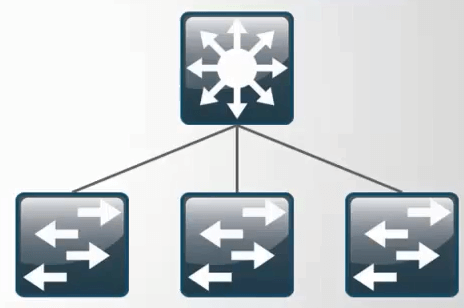
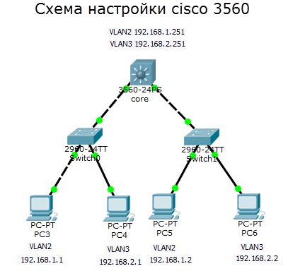
Предположим, что у меня коммутатор 3 уровня cisco 3560 24 порта, он выглядит как то вот так.
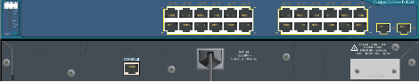
Он будет маршрутизировать трафик между vlan в моей локальной сети, и к нему допустим будут подключены 3 коммутатора 2 уровня модели OSI, уровня доступа, коммутаторы cisco 2960, а сам cisco 3560 будет выступать в качестве коммутатора уровня распределения. Напомню, что на втором уровне коммутируется трафик на основе mac адресов. Уровень доступа это куда подключаются конечные устройства, в нашем случае компьютеры, сервера или принтеры.. Ниже схема.
![Настройка vlan debian d-link [айти бубен]](https://wudgleyd.ru/wp-content/uploads/0/d/c/0dceeb9e9504d287b6e80efd53840094.jpeg)


![Настройка свитчей d-link через cli [база знаний - онлайн север]](https://wudgleyd.ru/wp-content/uploads/e/2/d/e2dc59a2df1d0f2e4dcbbf5199f0aa11.jpeg)

Что такое коммутатор второго уровня
Коммутатор второго уровня это железка работающая на втором уровне сетевой модели OSI
- Коммутирует трафик на основе мак адресов
- Используется в качестве уровня доступа
- Служит для первичного сегментирования локальных сетей
- Самая маленькая стоимость за порт/пользователь
В технической документации коммутатор второго уровня обозначает в виде вот такого значка
Что такое коммутатор третьего уровня
Коммутатор третьего уровня это железка работающая на третьем уровне модели OSI умеющая:
- IP маршрутизация
- Агрегирование коммутаторов уровня доступа
- Использование в качестве коммутаторов уровня распределения
- Высокая производительность
В технической документации коммутатор третьего уровня обозначает в виде вот такого значка
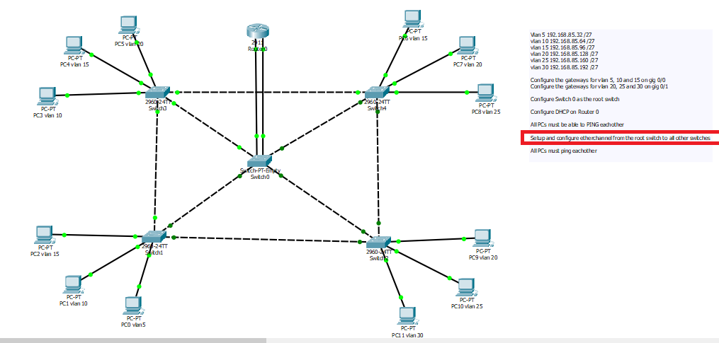
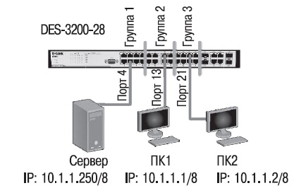
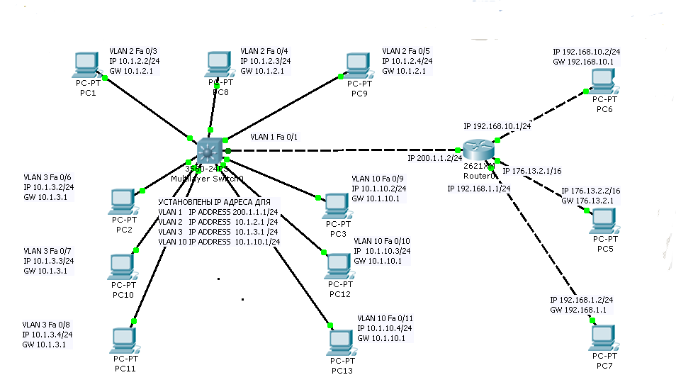
Помогать мне будет в создании тестового стенда программа симулятор сети, Cisco packet tracer 6.2. Скачать Cisco packet tracer 6.2, можно тут. Вот более детальная схема моего тестового полигона. В качестве ядра у меня cisco catalyst 3560, на нем два vlan: 2 и 3, со статическими ip адресами VLAN2 192.168.1.251 и VLAN3 192.168.2.251. Ниже два коммутатора уровня доступа, используются для организации VLAN и как аплинки. В локальной сети есть 4 компьютера, по два в каждом vlan. Нужно чтобы компьютер PC3 из vlan2 мог пинговать компьютер PC5 из vlan3.
С целью мы определились можно приступать. Напоминать, про то что такое vlan я не буду можете почитать тут.
Фильтры для свичей доступа
Настроить port security, запретив более одного mac адреса на порту (таким образом мы боремся с нежелательной и потенциально опасной ситуацией, когда клиент подключает в сеть провайдера не маршрутизатор, а коммутатор, сливая бродакстовый домен своей домашней сети с бродкастовым доменом провайдера)
config port_security ports 1-8 admin_state enable max_learning_addr 1 lock_address_mode deleteontimeout
Запретить STP на клиентских портах, чтобы пользователи не могли гадить в сеть провайдера BPDU пакетами
config stp version rstp
config stp ports 1-8 fbpdu disable state disable
Настроить loopback detection, чтобы 1) глючные сетевые карточки, которые отражают пакеты обратно и 2) пользователи, создавшие в своей квартире кольца на втором уровне не мешали работе сети
enable loopdetect
config loopdetect recover_timer 1800
config loopdetect interval 10
config loopdetect ports 1-8 state enable
config loopdetect ports 9-10 state disable
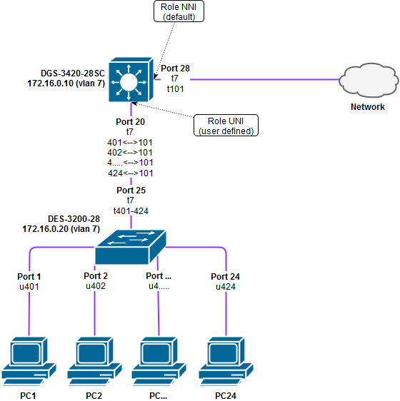
Создать acl, который запретит прохождение не PPPoE пакетов в USER vlan’е (блокируем DHCP, IP, ARP и все остальные ненужные протоколы, которые позволят пользователям общаться напрямую между собой, игнорируя PPPoE сервер).
create access_profile ethernet vlan 0xFFF ethernet_type profile_id 1
config access_profile profile_id 1 add access_id 1 ethernet vlan USER ethernet_type 0x8863 port 1-10 permit
config access_profile profile_id 1 add access_id 2 ethernet vlan USER ethernet_type 0x8864 port 1-10 permit
config access_profile profile_id 1 add access_id 3 ethernet vlan USER port 1-10 deny
Создать ACL, который запретит PPPoE PADO пакеты с клиентских портов (блокируем поддельные PPPoE сервера).
create access_profile packet_content_mask offset1 l2 0 0xFFFF offset2 l3 0 0xFF profile_id 2
config access_profile profile_id 2 add access_id 1 packet_content offset1 0x8863 offset2 0x0007 port 1-8 deny
И, наконец, включить STORM Control для борьбы с бродкастовыми и мультикастовыми флудами. Может показаться, что мы уже решили эту проблему, запретив не PPPoE трафик, однако есть но. В PPPoE первый запрос (на поиск PPPoE сервера) отсылается бродкастом, и если оборудование клиента в силу глюка, вируса или иных причин, посылает такие запросы интенсивно, это вполне может вывести сеть из строя.
config traffic control 1-8 broadcast enable multicast enable action drop threshold 64 countdown 5 time_interval 5
ACL для DES-3200-52
create access_profile profile_id 1 profile_name microsoft ip tcp dst_port_mask 0xFFFF
config access_profile profile_id 1 add access_id auto_assign ip tcp dst_port 135 port 1-48 deny
config access_profile profile_id 1 add access_id auto_assign ip tcp dst_port 139 port 1-48 deny
config access_profile profile_id 1 add access_id auto_assign ip tcp dst_port 369 port 1-48 deny
config access_profile profile_id 1 add access_id auto_assign ip tcp dst_port 445 port 1-48 deny

create access_profile profile_id 2 profile_name microsoft_udp ip udp dst_port_mask 0xFFFF
config access_profile profile_id 2 add access_id auto_assign ip udp dst_port 137 port 1-48 deny
config access_profile profile_id 2 add access_id auto_assign ip udp dst_port 138 port 1-48 deny
INTRODUCTION
The Switch can be managed through the Switch’s serial port, Telnet, or the Web-based management agent. The Command Line Interface (CLI) can be used to configure and manage the Switch via the serial port or Telnet interfaces.
This manual provides a reference for all of the commands contained in the CLI. Configuration and management of the Switch via the Web-based management agent is discussed in the Manual. Configuration and management of the Switch via the Web-based management agent is discussed in the User’s Guide.
Accessing the Switch via the Serial Port
The Switch’s serial port’s default settings are as follows:
•9600 baud
•no parity
•8 data bits
•1 stop bit
A computer running a terminal emulation program capable of emulating a VT-100 terminal and a serial port configured as above are then connected to the Switch’s serial port via an RS-232 DB-9 cable or RJ-45 console cable.
With the serial port properly connected to a management computer, the following screen should be visible. If this screen does not appear, try pressing Ctrl+r to refresh the console screen.
DES-3200-28 Fast Ethernet Switch
Command Line Interface
Firmware: Build 1.28.005
Copyright(C) 2010 D-Link Corporation. All rights reserved.
UserName:
PassWord:
Figure 1 — 1. Initial CLI screen
There is no initial username or password. Just press the Enter key twice to display the CLI input cursor − DES-3200-28:4#. This is the command line where all commands are input.
Setting the Switch’s IP Address
Each Switch must be assigned its own IP Address, which is used for communication with an SNMP network manager or other TCP/IP application (for example BOOTP, TFTP). The Switch’s default IP address is 10.90.90.90. Users can change the default Switch IP address to meet the specification of your networking address scheme.
The Switch is also assigned a unique MAC address by the factory. This MAC address cannot be changed, and can be found on the initial boot console screen – shown below.
|
Boot Procedure |
V1.00.006 |
——————————————————————————-
|
Power On Self |
Test …………………………………. |
100% |
||
|
MAC |
Address |
00-63-32-28-01-01 |
||
|
H/W |
Version |
B1 |
||
|
Please wait, loading V1.28.005 Runtime image ………….. |
100% |
Figure 1 — 2. Boot screen
The Switch’s MAC address can also be found in the Web management program on the Switch Information (Basic Settings) window in the Configuration folder.
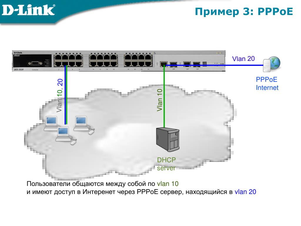
PPPoE только на Uplink
PPPoE — концентратор подключён к порту 26 коммутатора DES-3526, клиенты подключены к портам 1-25, MAC-адрес концентратора — 00-13-5F-AA-BB-CC.
Примечание: За полным описание протокола PPPoE обращайтесь к RFC 2516.
1. Создаём профиль ACL для разрешения PPPoE-пакетов от концентратора клиентам
create access-profile ethernet source_mac FF-FF-FF-FF-FF-FF ethernet_type profile 1
2. Разрешаем PPPoE-session-пакеты от концентратора клиентам
config access-profile 1 add access_id 100 ethernet source_mac 00-13-5F-AA-BB-CC ethernet_type 0x8863 port 26 permit
3. Разрешаем PPPoE-data-пакеты от концентратора клиентам
config access-profile 1 add access_id 200 ethernet source_mac 00-13-5F-AA-BB-CC ethernet_type 0x8864 port 26 permit
4. Создаём профиль ACL для разрешения PPPoE-пакетов от клиентов концентратору или серверу
create access-profile ethernet destination_mac FF-FF-FF-FF-FF-FF ethernet_type profile 2
5. Разрешаем широковещательные PPPoE-session PADI пакеты от клиентов
config access-profile 2 add access_id 100 ethernet destination FF-FF-FF-FF-FF-FF ethernet_type 0x8863 port 1-25 permit
6. Разрешаем PPPoE-session пакеты от клиентов к серверу
config access-profile 2 add access_id 200 ethernet destination 00-13-5F-AA-BB-CC ethernet_type 0x8863 port 1-25 permit
7. Разрешаем PPPoE-session пакеты от клиентов к серверу
config access-profile 2 add access_id 300 ethernet destination 00-13-5F-AA-BB-CC ethernet_type 0x8864 port 1-25 permit
8. Создаём профиль ACL для запрещения всех остальных PPPoE-пакетов
create access-profile ethernet ethernet_type profile 3
9. Запрещаем все остальные PPPoE пакеты
config access-profile 3 add access_id 100 ethernet ethernet_type 0x8863 port 1-26 deny config access-profile 3 add access_id 200 ethernet ethernet_type 0x8864 port 1-26 deny
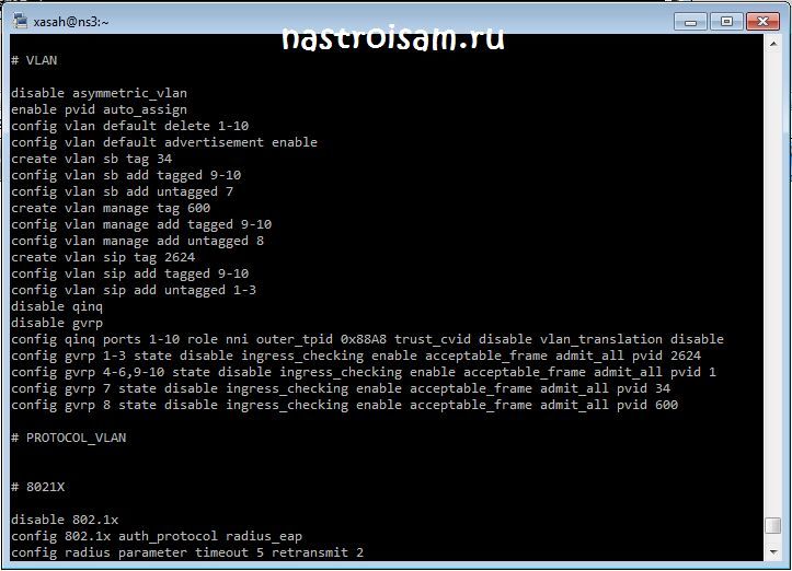
Основные команды для работы с коммутаторами D-Link серии DES и DXS
Просмотр основных характеристик коммутаторов dlink
show switch
Просмотр загрузки процессора (CPU)
show utilization cpu
Работа с конфигурацией
Просмотр текущей конфигурации
show config current_config
Просмотр конфигурации в nvram
show config config_in_nvram
Сохранение текущей конфигурации
save
Сброс к заводским настройкам
reset system
Выгрузка конфига на TFTP:
Обычный упр. свич
upload cfg_toTFTP 10.10.10.5 dest_file conf.cfg
Смарт свич
upload cfg_toTFTP 10.10.10.5 config.txt config_id 1
Настройка ip маски и шлюза
Настройка IP адреса и сетевой маски.
config ipif ipaddress [ip-адрес/маска]
Пример:
config ipif SYS ipaddress 192.168.5.10/24
Просмотр интерфейсов управления.
show ipif
Задание шлюза по умолчанию.
create iproute default
Пример:
create iproute default 192.168.5.1
Просмотра маршрута по умолчанию.
show iproute
Удаление маршрута по умолчанию.
delete iproute default
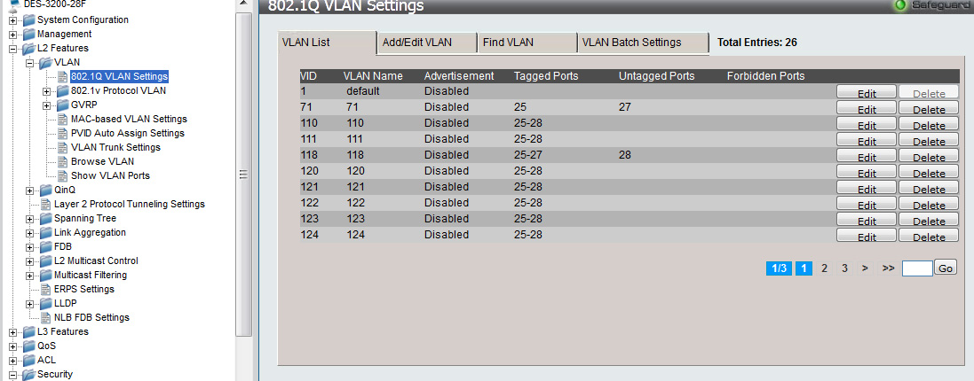
Настройка VLAN на коммутаторах dlink
Просмотр всех созданных vlan.
show vlan
Создание vlan.
create vlan tag
Пример:
create vlan USER tag 813
Добавление vlan на порты.
config vlan add
Пример:
config vlan USERTAG add untagged 1-3,5
config vlan USERUNTAG add tagged 8,10
config vlan USER add forbidden 9
В первом случае добавляется нетегированная (untagged) vlan на порты 1,2,3,5.
Во втором случае добавляется тегированная (tagged) vlan на порты 8,10.
В третьем случае запрещается прохождение vlan на 9-ом порту.


![Dlink:работа-с-vlan-на-коммутаторах-d-link [документы]](https://wudgleyd.ru/wp-content/uploads/a/d/e/aded44f37577885d6b957d6809aa109c.jpeg)


Настройка vlan управления коммутатора:
config ipif vlan ipaddress [ip-адрес/маска] state enable
Пример:
config ipif SYS vlan management ipaddress 192.168.2.40/24 state enable
Удаление default vlan со всех портов.
config vlan default delete 1-26
Настройка пользователей на коммутаторах dlink
Настройка имени пользователя и пароля.
create account
Пример:
create account admin admin
Enter a case-sensitive new password:********
Enter the new password again for confirmation:********
Просмотр учетной записи.
show account
Cменить пароль существующему пользователю.
config account
Пример:
config account admin
Enter a old password:********
Enter a case-sensitive new password:********
Enter the new password again for confirmation:********
Просмотр mac и arp таблиц
Просмотр таблицы mac-адресов.
show fdb
Просмотр таблицы mac-адресов для определенного порта.
show fdb port
Пример:
show fdb port 5
Просмотр arp табицы.
show arpentry
Просмотр диагностической информации по портам
Просмотр режимов работы портов (Speed, Duplex, FlowCtrl).
show ports
Просмотр ошибок на портe.
show error ports
Пример:
show error ports 3
Просмотр статистики по всем портам.
show utilization ports
Посмотреть инфу о SFP модуле
show ddm ports 10 status
Установка комментария на порт
config ports description
Пример:
config ports 10 description my-server
размер комментария может содержать до 32 символов и не должен содержать пробелы.
Настройка cisco 3560
Настройка cisco 3560, будет производится следующим образом. так как наше ядро должно маршрутизировать внутренний локальный трафик, то мы должны создать такие же vlan, задать им ip адреса, так как они будут выступать в роли шлюзов по умолчанию, а так же trunk порты.
Начнем с транк портов, у нас это gig 0/1 и gig 0/2.
enable
config t
заходим в настройку интерфейса gig 0/1 и gig 0/2
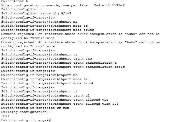
int range gig 0/1-2
Попытаемся включить режим транка
switchport mode trunk
но в итоге вы получите вот такую подсказку: Command rejected: An interface whose trunk encapsulation is «Auto» can not be configured to «trunk» mode. Смысл ее в том, что вам сначала предлагают включить инкапсуляцию пакетов. Давайте настроим инкапсуляцию на cisco 3560.
switchport trunk encapsulation dot1q
Теперь укажем режим и разрешенные vlan
switchport mode trunk
switchport trunk allowed vlan 2,3
Сохраним настройки Cisco
do wr mem
Далее создадим vlan и назначим им ip адреса, которые будут выступать в роли шлюзов.
vlan 2
name VLAN2
exit
vlan3
name VLAN3
exit

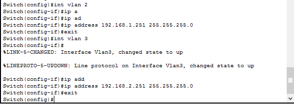
Назначим ip адреса для каждого из них, напомню для vlan 2 это 192.168.1.251/24, а для vlan 3 192.168.2.251/24
int vlan 2
ip address 192.168.1.251 255.255.255.0
no shutdown
exit
int vlan 3
ip address 192.168.2.251 255.255.255.0
no shutdown
exit
Теперь включим маршрутизацию между vlan, делается это командой
ip routing
do wr mem
DES-3200-10 базовая настройка
D-Link DES-3200 — дешевый управляемый L2-коммутатор(свитч), имеющий очень хороший функционал за умеренную стоимость. Всвязи с этим провайдеры очень нередко употребляют данную модель как для организации каналов связи, так и для подключения абонентов широкополосного доступа (ШПД).
В качестве примера для базисной опции разглядим модификацию DES-3200-10, имеющую 8 медных 10/100 портов RG-45 и 2 комбинированных 1000BASE-T/SFP порта. Адресок Web-интерфейса коммутатора — http://10.90.90.90, соответственно для того чтоб попасть на него — Вам нужно прописать на сетевой плате Айпишник из той же сабсети что и сам свитч — к примеру 10.90.90.91 . По дефлоту на коммутаторе нет юзера и пароля на доступ к интерфейсу опции, потому в окне запроса логина и пароля не пишем ничего а просто жмем OK. Самый 1-ый шаг который следует сделать — настроить доступ к управлению свитчем для этого прописываем Айпишник коммутатора из собственной сети. Для этого идём в раздел Configuration пункт IP Address Settings:
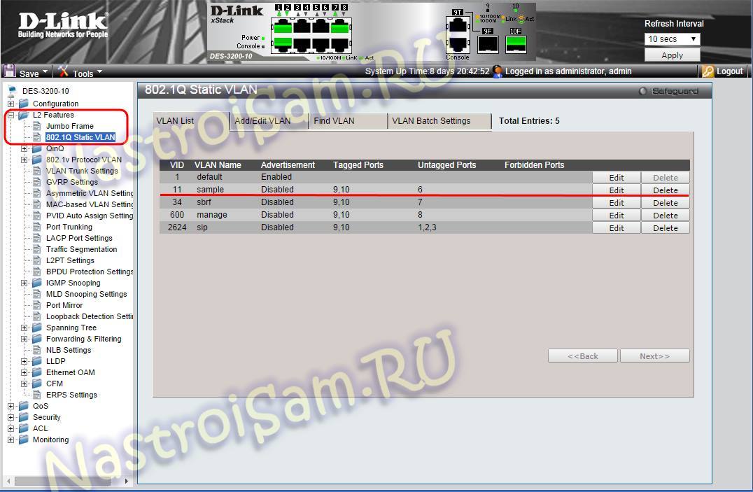
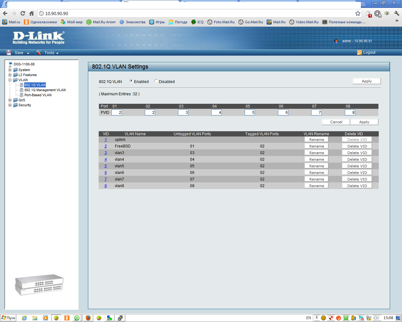
В случае использования в сети DHCP-сервера — ставим галочку DHCP и жмем Apply. Если же адресация в Вашей сети статическая — ставим галку Static прописываем собственный Айпишник, маску, шлюз и жмем Apply. После этих манипуляций доступ к свитчу с компьютера пропадёт до того времени, пока Вы не перенастроите Айпишник на сетевой плате компьютера в ту же сабсеть. В случае эксплуатации D-Link DES-3200 в сети с внедрением Vlan’ов (802.1q) Вам нужно будет прописать управляющий Vlan. Перебегаем в раздел L2 Features пункт 802.1Q Static Vlan:
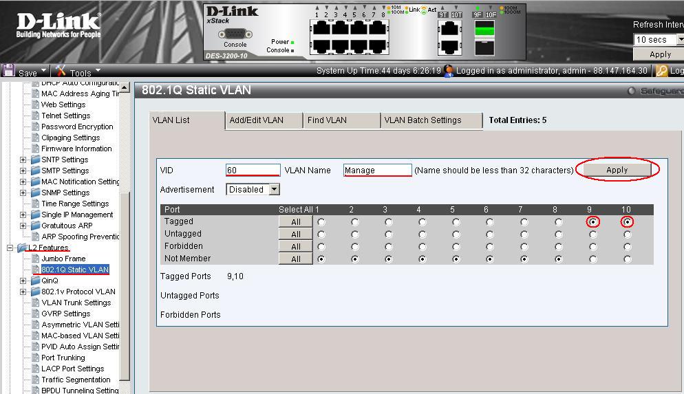
В этом меню представлены настроенные на устройстве Vlan’ы и «привязанные» к ним порты. По дефлоту на устройстве только один дефолтный Vlan с идентификатором 1. Для прибавления собственного Vlan’a перебегаем на вкладку Add/Edit Vlan:
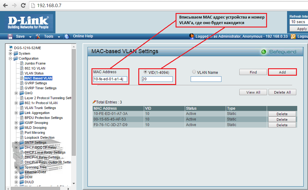
В поле V >tagged порта — 9 и 10, т.е. ставим напротив их галку Tagged и жмем Apply. Примечание: Если необходимо «привязать» к Vlan’у оконечный аксессный untagged порт — то ставим напротив подходящего порта галку Untagged. После этих манипуляций коммутатор по этим портам, при подключении к ним компьютера, станет недоступен. Сейчас нужно указать в настройках что 60-й Vlan управляющий — перебегаем снова в раздел Configuration пункт IP Address Settings:
В поле Management Vlan Name пишем имя управляющего Vlan’a — в нашем случае manage . И жмем Apply. Сейчас управление с присоединенного компьютера пропадёт совсем и коммутатор DES-3200-10 будет доступен только по управляющему Vlan 60.
Примечание: Если после опции управления устройство труднодоступно в сети по управляющему Vlan’у (хотя прописано всё правильно) или после недолговременного времени сбрасывает опции управления — обновите прошивку коммутатора с официального сервера. 4-ый шаг — настроим доступ к настройке DES-3200 через авторизацию. Для этого перебегаем в раздел Configuraton -> User Accounts:
Создаем нового юзера с полными правами Админа — для этого в поле User Name вводим имя — к примеру admin, права Access Rights — Admin и два раза вводим пароль в поля Password и Commit Password. Жмем Apply.
В качестве последнего этапа непременно сохраните опции нажатием кнопки Save -> Save All верхнем левом углу веб-интерфейса коммутатора:
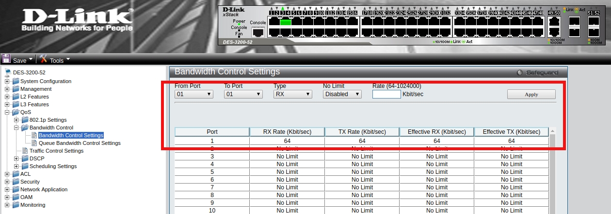
на этом базисная настройка L2-коммутатора DES-3200 завершена. В качестве постскриптума: Очень нередко при базисной настройке появляется необходимость принудительно выставить скорость на каком-нибудь из портов. Делается это в разделе Port Configuration -> Port Settings:


![Настройка vlan debian d-link [айти бубен]](https://wudgleyd.ru/wp-content/uploads/c/a/9/ca9be71b10612fcccda44f12e1ed0856.jpeg)
![Настройка свитчей d-link через cli [база знаний - онлайн север]](https://wudgleyd.ru/wp-content/uploads/6/5/a/65af3c2c3fa8c6958cfd6daf9d56dafd.jpeg)
![Настройка свитчей d-link через cli [база знаний - онлайн север]](http://wudgleyd.ru/wp-content/uploads/4/0/9/409a274206d502c9ea4d9d2831380551.png)